I've had a chance to finish and try out the latest iteration of quadruped joints and frame, and I'm happy to say that I think they're a significant improvement. As in, IT CAN STAND UP NOW.


For newer readers, the quadruped's name is ACE (Ambulatory Canine Emulator), and I first started trying out quadruped designs in my late college years. I was thinking that the interesting part would be designing or training the walk cycle, but I haven't even gotten that far yet due to difficulties with the mechanical side of the project. It turns out that you need a decent degree of precision for something like this, and that can be hard to get from homemade parts and salvaged materials. Specifically, I had big trouble with 1) joints moving out of plane and 2) parts of the structure flexing. A little bit of variability or unconstrained motion may not seem like a big deal, but once you consider the contributions of multiple joints in a leg *and* a bending frame, you get a robot that can't stand up.
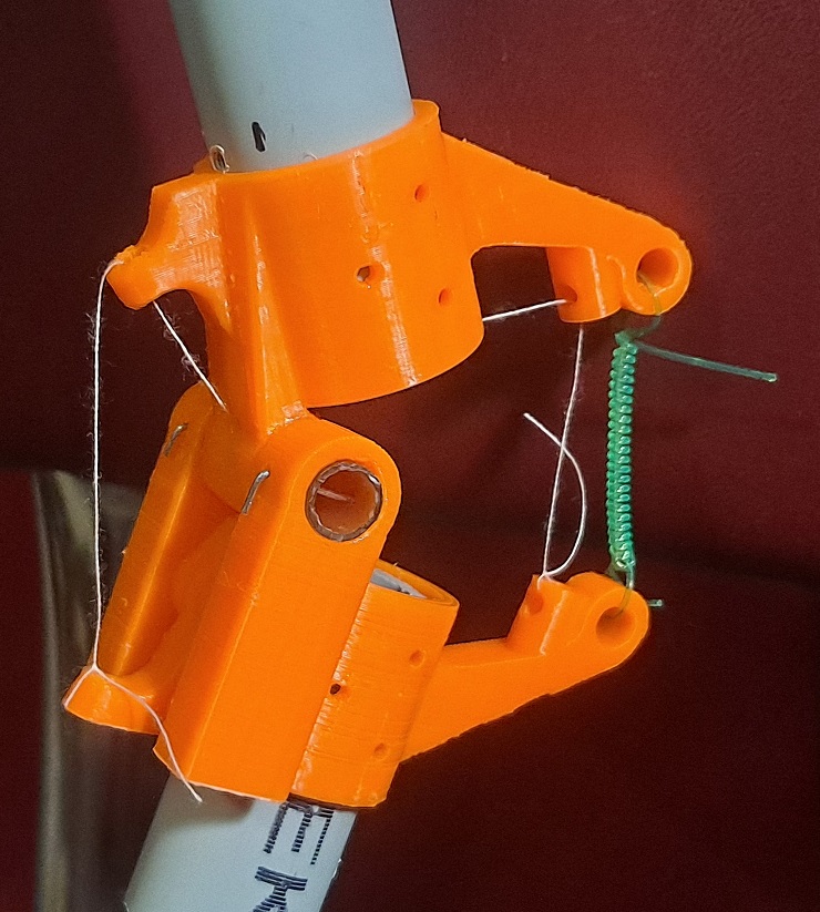 |
| Prototype of elbow/hock joint with temporary homemade spring. |
This project has been dormant for a while. Here is a photo of some previous joint design attempts (along with previous lab assistant d'Artagnan, who has since passed on). I didn't have a 3D printer yet at the time, so I was still limited in what I could manufacture. In some ways, the elbow/hock joints described in that blog post were a real improvement: the metal tubing shaft + ballpoint pen sleeve combination provided smooth, constrained rotation. The problem was the method of attaching it to the leg bones. Suspending the two halves of the joint on wires didn't work out; they just weren't rigid enough for the application.

Throw in further issues with the shoulder/hip joints and the frame/upper body (which were so embarrassing I don't think I even blogged about them) and the attachment of the motors to the legs, and it was hard to even get the robot to passively stand in an upright position. Some joint was bound to start wobbling or folding sideways and tip the whole thing off balance. The photo below shows my best effort to pose it for a robot "group picture." It isn't standing at full height, at least one leg is tilted out of plane, and it's probably still ready to fall over if someone blows on it too hard.

This latest round of work was a complete redesign of the joints and structural elements. I reused the PVC conduit legs, the same motors, and the wooden dowel sections from the original frame, and that was about it. The old version had each motor mounted above the joint it was to operate, with a linear actuator attachment; this would convert the motor's rotary motion into linear motion and push/pull one "bone" relative to the other. This meant one of the motors was attached directly to the upper half of the leg. In the new version, I decided to actuate the joints with differential pairs of tendons, and put all the motors up on the frame - which means there isn't a heavy, clunky motor hanging off each leg. I designed and printed plastic joint couplers intended to solve the problem of unconstrained motion. I gave some thought to gravity-countering tension elements for the first time, and included attachment points for them. And I eschewed screws in favor of bent/wrapped wire connections. I used these to good effect in Atronach, and they're my current favorite way of joining 3D-printed parts. The only screws in the new design go through holes in one of the frame pieces and into the ends of the wooden dowels.
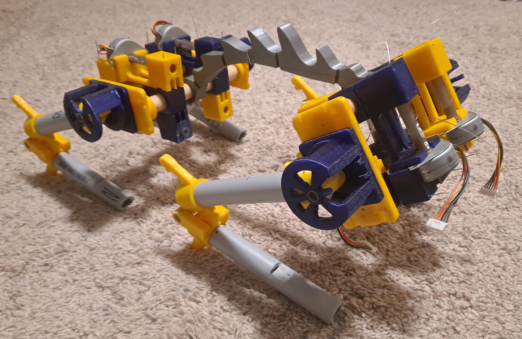 |
| The latest version of ACE "lying down." |
The 3D printer's ability to produce almost arbitrary shapes was a big help here, but I also knew I would have some trouble getting smooth, precise motion out of printed joints, just by the nature of the thing. Tolerances aren't guaranteed to be perfect, and layer lines mean the surfaces will always be a little rough. So I included some of my old friends: chopped-up ballpoint pens. (This is seriously the most convenient way I know of to get rigid plastic tubing.) I designed each joint to use part of a pen as a shaft, with the 3D printed pieces wrapping around it to provide both the rotating shaft collar and the fixed mounting point.
The elbow/hock joints are simple hinges, with a range of motion somewhat less than 180 degrees. They are designed to join two tubes in the same plane. For the shoulder/hip joints, I came up with this design that has the leg tube suspended from the shaft and rotating between two guides. The total contact surface is fairly large, which I hope will help reduce any out-of-plane rotation.


I also had to think about the routing of the tendons while I was designing all this. The tendons that work the elbow joint go up the inside of the hollow upper leg bone, through a hole drilled in the "fixed" part of the shoulder joint shaft, and out the end of the shaft to their motor's axle. That means they don't interfere with, or change length during, motion of the shoulder joint - because they're routed parallel to its axis of rotation. Control of the two joints can be fully independent as a result. Shoulder joint tendons feed through holes in the solid pieces that connect the two joint guides (so that they'll pull in the right direction), then turn ninety degrees and pass through holes in the joint's base to reach their motor.
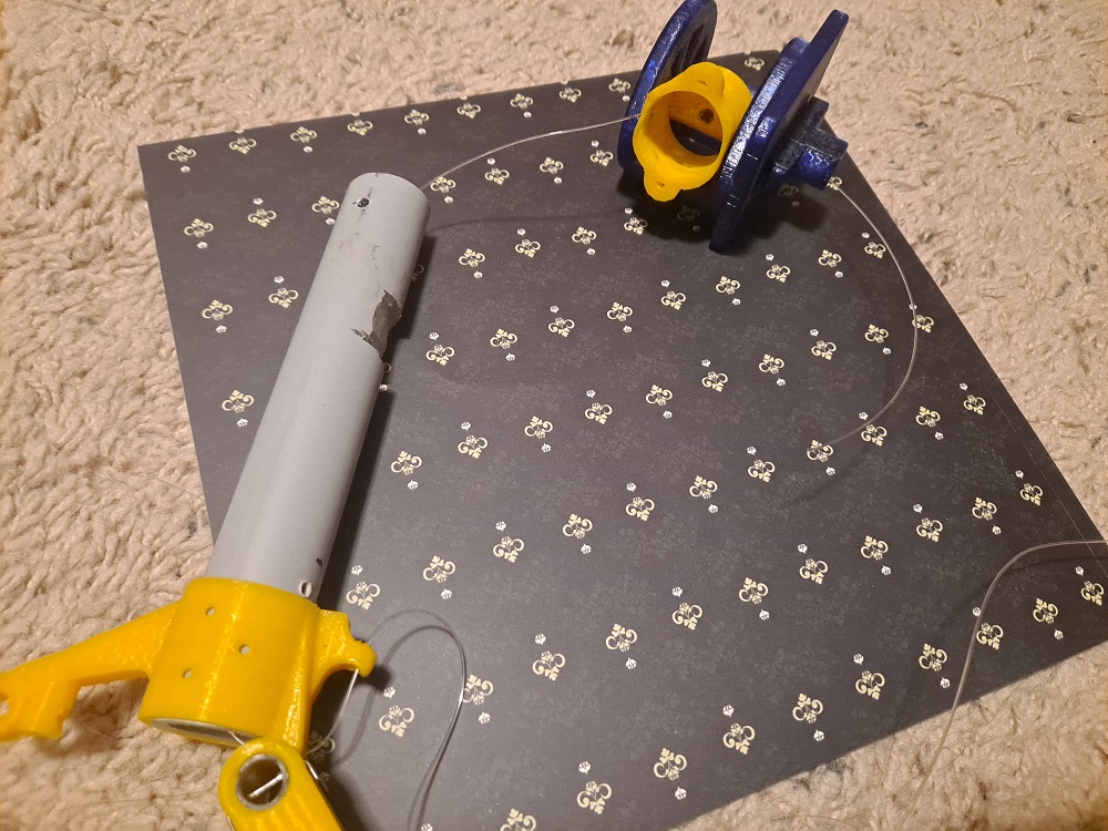 |
| Elbow tendon routing through shoulder |
I designed all the pieces a little too tight, and sanded them to fit. So most things push or snap together well enough that it maintains a lot of integrity even without all the wires installed. Everything has options for a wire connection, though, because I know how important it is to guarantee that pieces don't unexpectedly move (and my first bitter lesson was that you can never count on glue). Printed pieces that join have matching holes; the leg joints wire up to drilled holes in the PVC.
So now, the moment of truth. Does it stand? Behold!
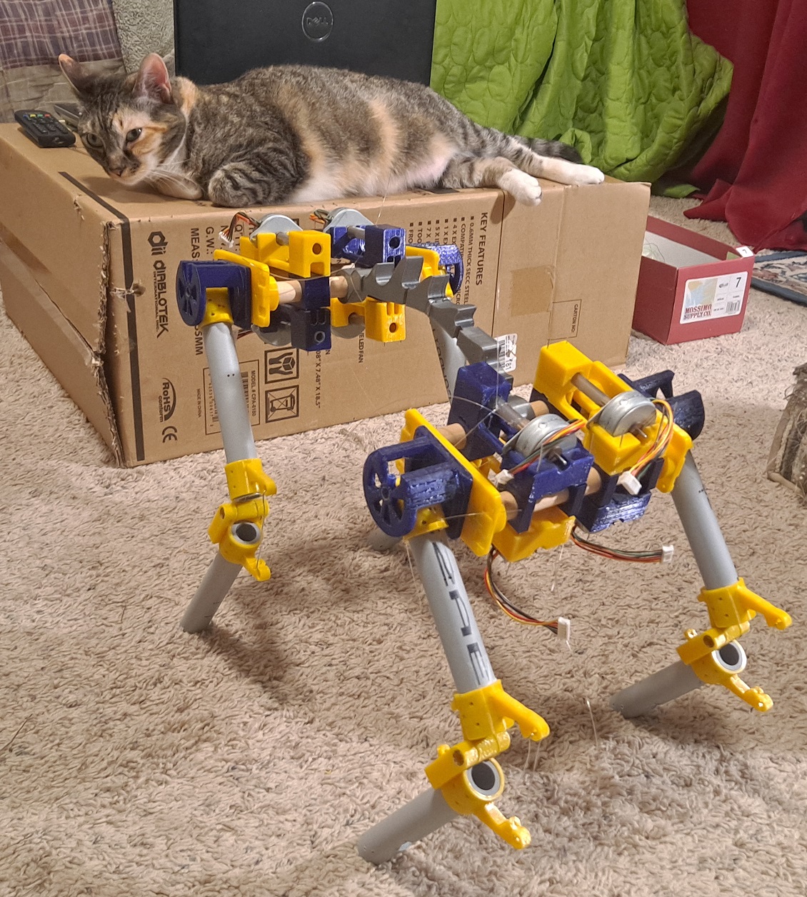
Unlike the previous version, whose linear actuators would basically lock the joints in position, this one kneels under its own weight. The unpowered holding torque of the motors isn't large enough to keep the joints extended. Tension elements will help with that, but I don't have any yet (except one spring I made for a test). So I used wires to hold the elbow/hock joints open for purposes of that photo. Most of the tendons aren't installed yet either, so three of the four shoulder/hip joints were free to rotate ... and I still got it to stand. Wow. I was half afraid I'd never get here.

Now that I've built everything, I've already got ideas for how to make the next round of joints better. But Atronach should get some attention now, plus I'd like to take a step back and try to improve my 3D printing technique. I hope to return to ACE next year and either try some real actuation, or decide these motors don't have an adequate torque-to-weight ratio and redesign the motor cradles to hold something else. (If I need new motors, I'll only have to change that one part, which is pretty nice.)
Until the next cycle,
Jenny
Well done! I always figured cables to joints were a good avenue of research, based on how fingers work. Speaking of, my hands are very stiff from work and temperature, please forgive me being brief.
ReplyDeleteAlso, who's the cute new lab assistant? Or is that a standard issue reference cat for scale? ;)
Thanks! That is Ursula. She very much enjoys being in the middle of whatever I'm doing.
Delete