Showing posts with label Project Atronach. Show all posts

Sunday, May 17, 2026

Atronach's Eye 2026

Wait, I thought this got finished? Yes, so this year it was time to build a second, better one. I didn't change the mechanical design much; it has some minor improvements I had already worked into the 3D models after finishing the last one, but it's the same in substance. What I really wanted was a chance to try out one or two of my new cameras. Given the way the eye is assembled, replacing the camera is a fairly big deal. So instead of pulling apart the mostly-functional eye I already had, I made a whole new one. This has the added benefit of giving me a demonstration model that I can take places, while I leave the flagship one parked on my living room wall.

The original eyeball's camera is a "300K pixel USB 2.0 mini webcam," like this one. At $7-$9, they're cheap enough to buy in bulk, AND they come in a small enough case to fit comfortably inside the eyeballs. Unfortunately, the image quality you get for that price seems pretty poor. The low resolution isn't the real issue (there's no need for megapixels when you're only doing basic motion detection). It's that the output seems just plain noisy, especially under lower-light conditions. I also wanted to try a wider field of view. It's very easy for the existing eyeball to completely miss a person in the room because it's all the way over on one side of its range of motion staring at the side wall, or even because the person walks through its visual range too fast.

My two new cameras are an ELP-USB30W02M-MHV120 (120 degree FOV, 640x480 pixels, $28 now but I got it for $14) and another ELP model with a fisheye lens that seems to no longer be available (170 degree FOV, 1080P, $27.50 - this one is similar but more expensive.). They're both what I want to call "card cameras," consisting of a naked square circuit board with the lens sticking out of one side and a cord coming out the other. In that sense they're similar to the card cameras sold specifically for use with Raspberry Pis, but they have USB cables instead of short ribbon cables - important for compatibility with the eyeball's interior layout. It also made the cameras easier to try out with my laptop when I first got them.

And in initial tests, the output from both seemed significantly cleaner. I could run background subtraction without seeing a whole lot of imagined "motion patches" created by especially noisy regions of the image. Without as many noise problems to deal with, I was able to reduce the OpenCV MOG2 background subtraction algorithm's "history" parameter and get rid of the running average I was applying to my computed center of motion value. This made the motion tracking less laggy and more responsive.

A mechanical eyeball in 3d-printed plastic. It's a red sphere with a camera lens sticking out the front, encased in a cradle that sits in a case/backshell containing two motors mounted in gearboxes, a Raspberry Pi, and two driver boards.

Printing and assembling a whole new eyeball from scratch took much longer than I'd anticipated. I added features to the previous one gradually, and that left me with a poor grasp of how complex the build is when started from the beginning. Each motor now has a gear pair for a little more torque, which is helpful at the edges of the range of motion. A small downside is that they seem to make the eyeball noisier.

It was all so much work that I still haven't had time to wire and install the limit switches! So the new eyeball is operating by "dead reckoning" of where it's pointing at the moment. But I got enough of it put together to test the motion tracking, and I think it's finally working reliably! It certainly performs better than the original. I was even able to activate the up/down dimension of motion without issue. That's disabled in the original eyeball, because it was too prone to get stuck staring at the ceiling and whatnot. The expanded field of view is also a big help.

So I still have to finish up the last bits of the construction, but on the whole I'm very pleased. A decade ago, I never believed that following motion would be this hard ... but that's what I get for cheaping out on the cameras, I guess!

Until the next cycle,
Jenny

Tuesday, December 30, 2025

Year in Review 2025

As 2025 slips into the history books, I continue my tradition of looking back and considering what I accomplished and how I spent my time. This year I set a goal of spending 1000 hours on my personal hobbies and chores. That's over 19 hours a week, and more than I've logged in any previous year since I started keeping track. Well, I did it. I made it to that beautiful round number. And I don't think I'll try to do it next year. 

Art of a flock of brown birds (swallows, perhaps) swooping up from the lower left. A single bird has gotten ahead of the the flock and appears about to touch a sun-like fiery globe in the upper right corner. The background is abstract; the birds are leaving a swooping gray wake on the left side, pale blue clouds surround the sun, and the rest of the scene is a flat light blue or white.
New Years' card by H. Th. Wijdeveld, 1973.

It helped me play catch-up and get a lot of little issues under control. It gave me time to start introducing a new project without neglecting my existing ones. I had room for creativity and all the maintenance-and-repair tasks that often go by the wayside. I also, at times, felt very pressured and stressed out. Keeping up with the 1000-hour target while maintaining my social life was pretty doable ... so long as I was at the top of my game and nothing unexpected came up. I felt as though I didn't have room in my life for so much as an "off" day. And this year there were plenty of off days, for personal reasons I won't get into. So I'm rather proud of pulling off the goal anyway, but for my long-term health and happiness, I think I should leave more room in the margins for the near future.

I spent about the same amount of time on Acuitas as I did last year: 365 hours. So I'm poetically averaging one hour of work on him for every day in the year. Acuitas accomplishments included:

*Introduction of rudimentary trial-and-error learning methods, followed by a demo of Acuitas playing a text conversion of the Allergic Cliffs puzzle, from _Logical Journey of the Zoombinis
*Text Parser improvements leading to transfer of all benchmark sentences out of the "unparseable" category
*Introduction of some numerical reasoning and ability to track multiple instances of a type in the narrative scratchboards
*Continued improvements across narrative understanding and conversational ability
*Revitalization of the semantic memory visualizer and question generator

Screenshot from a Windows 95-era video game with animated sprites and a painted background. Four zoombinis, who look like little blue orbs with hair, eyes, nose, and locomotion devices attached, are gathered around a hole dug in the ground, looking conspiratorially at each other.

Time put into my fiction writing also came out to be very similar, compared to last year. The big news was publication of my first story in a paying webzine, "Peacemaker's First Strike" in Abyss & Apex. Major thanks to the editors at A&A, and to everyone who shared this story around and helped get it in front of more eyes. There has since been another win on the publication front, but I don't think I should make it public until there is ink on a contract, so you'll all have to wait a bit to hear about that one.

I wrote two new stories in 2025: "Heartspeed," a strange dystopian sci-fi about a bicycle courier who teams up with an outlaw AI to fudge her performance data, and "Seeing," a fantasy about four pilgrims seeking a temple which is only findable by those who've seen it before - each with a different strategy and petition.

The major beneficiaries of my extra hobby hours were Robotics, which jumped from 112 to over 140, and Studying, which went from 23 to 60. The latter led directly into the selection and planning of the new Physics Project. Robotics accomplishments spanned multiple projects:

A fluid bladder with the plastic cylinder/piston assembly it is designed to actuate in the background, attached to the syringe, and partially inflated, showing all five pleats.
Five-pocket accordion fluid bladder test

*I finished Atronach's Eye! Well, softly finished - the eye reached a stage of development where I could have it operating on my wall. Improvements are planned, and I put quite a bit of time into trying out new motion detection algorithms, computation speed improvements, and cameras.
*I continued my hydraulics experiments with better pump motors, improvements to bladder design and manufacturability, and actuator design. I progressed this technology development far enough to plan and price out a full robot design, which I hope to move ahead with next year.
*I ran enough motion tests on ACE to decide it was going to need better motors, then purchased and tried out some options.

As planned, I trimmed time spent on the blog this year, keeping my investment under 55 hours, but I've still managed to put up two posts per month. I achieved this by focusing more on my own projects and not doing a research-heavy article series. I spent almost no time on art. I'd like to get back to it someday, but higher-priority things have to be finished first.

A pile of carrots (with tops) laid out on a rug, with a tricolor tabby cat snooping on them in one corner.

2025 was a good garden year. I brought in over 10 lb. of potatoes and successfully grew carrots for the first time. I also seem to have cleared the blight from the main apple tree, though due to previous years' damage it did not produce well. The house and yard are properly maintained, and I've repaired my broken knick-knacks and tools. Time spent on Finances nearly doubled because I sorted out some investments.

Last but not least, I put quality time into some gifts for friends and family. I pushed my 3D printing skills making these, and the Vyper continues to be a solid budget workhorse.

Photo of a cryptex - a cylindrical combination lockbox with wheels that form a password when properly rotated. This one is partly open, showing the interior tube where you can store secrets. The endcaps are matte brown with silver accents, and the letter wheels alternate in marble and ivory colors.
Cryptex by Cees on Printables
 
A 3d-printed plastic model of a Trans Am, in "milk white" with silver metallic parts and black tires, plus painted windows and details. This is a rear/side view showing the rear grille insert.
"Foldable Pontiac Firebird Trans AM 1982" by GOODesign on Fab365

Thank you all as always for following along. I wish you the best 2026 can bring.

Sunday, May 11, 2025

Further Thoughts on Motion Tracking

Atronach's Eye may be operating on my wall (going strong after several months!), but I'm still excited to consider upgrades. So when a new motion detection algorithm came to my attention, I decided to implement it and see how it compared to my previous attempts.

MoViD, with the FFT length set to 32, highlighting and detecting a hand I'm waving in front of the camera. The remarkable thing is that I ran this test after dusk, with all the lights in the room turned off. The camera feed is very noisy under these conditions, but the algorithm successfully ignores all that and picks up the real motion.

I learned about the algorithm from a paper presented at this year's GOMACTech conference: "MoViD: Physics-inspired motion detection for satellite image analytics and communication," by MacPhee and Jalai. (I got access to the paper through work. It isn't available online, so far as I can tell, but it is marked for public release, distribution unlimited.) The paper proposes MoViD as a way to compress satellite imagery by picking out changing regions, but it works just as well on normal video. It's also a fairly simple algorithm (if you have any digital signal processing background, otherwise feel free to gloss over the arcane math coming up). Here's the gist:

1. Convert frames from the camera to grayscale. Build a time series of intensity values for each pixel.
2. Take the FFT of each time series, converting it to a frequency spectrum.
3. Multiply by a temporal dispersion operator, H(ω). The purpose is to induce a phase shift that varies with frequency.
4. Take the inverse FFT to convert back to the time domain.
5. You now have a time series of complex numbers at each pixel. Grab the latest frame from this series to analyze and display.
6. Compute the phase of each complex number - now you have a phase value at each pixel. (The paper calls these "phixels." Cute.)
7. Rescale the phase values to match your pixel intensity range.

The result is an output image which paints moving objects in whites and light grays against a dark static background. I can easily take data like this and apply my existing method for locating a "center of motion" (which amounts to calculating the centroid of all highlighted pixels above some intensity threshold).

My main complaint with the paper is its shortage of details about H(ω). It's an exponential of φ(ω), the "spectral phase kernel" ... but the paper never defines an example of the function φ, and "spectral phase kernel" doesn't appear to be a common term that a little googling will explain. After some struggles, I decided to just make something up. How about the simplest function ever, a linear function? Let φ(ω) = kω, with k > 1 so that higher frequencies make φ larger. Done! Amazingly, it worked.

Okay, math over. Let me see if I can give a more conceptual explanation of why this algorithm detects motion. You could say frequency is "how fast something goes up and down over time." When an object moves in a camera's field of view, it makes the brightness of pixels in the camera's output go up and down over time. The faster the object moves, the greater the frequency of change for those pixels will be. The MoViD algorithm is basically an efficient way of calculating the overall quickness of all the patterns of change taking place at each pixel, and highlighting the pixels accordingly.

It may be hard to tell, but this is me, gently tilting my head back and forth for the camera.

My version also ended up behaving a bit like an edge detector (but only for moving edges). See how it outlines the letters and designs on my shirt? That's because change happens more abruptly at visual edges. As I sway from side to side, pixels on the letters' borders abruptly jump between the bright fabric of the shirt and the dark ink of the letters, and back again.

The wonderful thing about this algorithm is that it can be very, very good at rejecting noise. A naive algorithm that only compares the current and previous camera frames, and picks out the pixels that are different, will see "motion" everywhere; there's always a little bit of dancing "snow" overlaid on the image. By compiling data from many frames into the FFT input and looking for periodic changes, MoViD can filter out the brief, random flickers of noise. I ran one test in which I set the camera next to me and held very still ... MoViD showed a quiet black screen, but was still sensitive enough to highlight some wrinkles in my shirt that were rising and falling with my breathing. Incredible.

Now for the big downside: FFTs and iFFTs are computationally expensive, and you have to compute them at every pixel in your image. Atronach's Eye currently runs OpenCV in Python on a Raspberry Pi. Even with the best FFT libraries for Python that I could find, MoViD is slow. To get it to run without lagging the camera input, I had to reduce the FFT length to about 6 ... which negates a lot of the noise rejection benefits.

But there are better ways to do an FFT than with Python. If I were using this on satellite imagery at work, I would be implementing it on an FPGA. An FPGA's huge potential for parallel computing is great for operations that have to be done at every pixel in an image, as well as for FFTs. And most modern FPGAs come with fast multiply-and-add cells that lend themselves to this sort of math. In the right hardware, MoViD could perform very well.

So this is the first time I've ever toyed with the idea of buying an FPGA for a hobby project. There are some fairly inexpensive FPGA boards out there now, but I'd have to run the numbers on whether this much image processing would even fit in one of the cheap little guys - and they still can't beat the price of the eyeball's current brain, a Raspberry Pi 3A . The other option is just porting the code to some faster language (probably C).

Until the next cycle,
Jenny

Tuesday, February 11, 2025

Atronach's Eye 2025 (Complete?)

As of last year I had worked all the major bugs out of my motion-tracking eyeball, but I still couldn't consider it finished. I wasn't ready to hang it on the wall and let it operate yet, due to one last issue: thermal concerns.

The mechanical eyeball in its colorful case, mounted on a beige wall. There's a couch in the foreground, and the eyeball's power cord is visible hanging down behind the couch. Also visible is the back half of a tricolor tabby cat, who is trying to burrow in between two layers of blankets on the back of the couch.
It's installed on the wall! It's operating continuously! It's done! The Lab Assistant gets to take a nap!

The eyeball's motion is driven by two unipolar stepper motors, each of which is powered from one of my dirt-simple stepper motor controllers. These are custom PCBs that I got manufactured many years ago. They were very inexpensive, and they only have two control wires (a nice thing for connecting motors to embedded processors with a limited number of general purpose IO). But that also means they don't have a power enable. Even if the control inputs are static and the motors aren't moving, some of their coils remain energized. That means they can exert their holding torque, which keeps the drive shaft in place and resists any external forces that try to turn it. But that wasn't something the eyeball needed (it naturally stays in position when unpowered). And during tests, I noticed that the motors got quite hot: enough to be uncomfortable to touch and make the plastic case smell.

I didn't like the thought of leaving the eye turned on with the motors baking themselves and everything else in the case in their own heat day in and day out. I doubt it would qualify as a fire hazard or anything serious like that, but in addition to wasting a small amount of electricity, it could reduce the lifetime of the parts. So I wanted to be able to cut all power to the motors when the eye wasn't active.

My solution was a standard relay. I bought some of these nice little breakout boards from DIYables that have the relay already mounted with connectors and a couple of indicator LEDs, and spliced one into the motor power input path of both motor controllers.

Then I added code to the eyeball software to turn the relay on and off. I wanted to strike a balance between letting the motors heat too long, and clicking the relay on and off constantly. So the software turns the motors off if no moving object to track has been seen in view for a certain amount of time. I also threw in darkness detection; the eye will stop trying to track motion if the average brightness of the scene is too low to see properly. (So it won't move around and make little noises in the middle of the night because the camera picked up some low-light noise.) Both features worked very well. The eye reliably deactivates when I leave the room (so long as there isn't something else moving around, like the flames in the fireplace) and when the lights are out or too dim.

In the dark, the indicator LEDs on the Raspberry Pi and the relay board diffuse through the white parts of the case and turn the eye into a low-key nightlight. I wasn't really expecting this, but hey: it still has a function when it's not looking at stuff.

In the end, I got to do what I always wanted: hang the eye on the wall and let it be an always-on fixture in the house. Further tweaks and upgrades to the software are possible, but I'm calling it finished because it's finally operating. It has been on the wall trying to look at me, the Lab Assistant, and other motion sources for at least a couple weeks of total up-time. Hearing it "wake up" as I pull open the curtains has become part of the morning routine.

There will almost certainly be another version, because there are plenty of things I could improve. I already applied a bunch of little enhancements to the 3D models of the case parts late last year. But this is the first Atronach's Eye iteration that could be said to realize my original vision (cough) for the project, if imperfectly. I'm also thinking about what else I can do with it. Atronach could theoretically tell Acuitas whether there's somebody in the room, for instance. Mmmm.

Until the next cycle,
Jenny

Saturday, December 28, 2024

Year in Review 2024

With 2025 waiting in the wings, I am casting an eye back over 2024 and finding that it looks pretty shiny from here. Overall, it felt like there were fewer extraneous disruptions and distractions than there have been for the past few years - I got the chance to dig in to my hobbies and push hard. I also feel I did a good job of moving existing projects toward completion and taking a few overdue items off the backlog, instead of just starting new work.

Fireworks: three "artillery shell" style bursts in a loose row, two gold with blue accents, one white. No horizon is visible. Photo of fireworks in Bratislava by Ondrejk, public domain.

Per my personal tracking, I've logged more hours of total "work" than I did last year, and kept the creation/maintenance ratio above 3x ... just barely. Monitoring my own time usage over a long period raises some interesting flags. For example, I spent more time on my blog articles this year than I spent writing and publishing short fiction, by 6+ hours. (Those "AI Ideology" articles were a lot of work. Writing about real people's viewpoints and trying to be critical but fair eats serious hours.) I don't think I want the blog to be taking that much, so I'm not planning an in-depth series for 2025, and I'll probably let my article rate drop below two per month. But where writing tasks are concerned, even the blog loses the time hog prize to journaling. I'm a little uncomfortable with the fact that recording my life uses so much of it up, but I also really like journaling (and it's easy, so if I dumped it, some of those hours might go to recreation instead of harder tasks). Other mundane time-stealers are on the small side, but still galling. I logged more hours on food preparation than on studying, and more on housecleaning than on art.

Acuitas remains the king of all my hobbies at 360+ hours invested. That's a good number - I found more time for him in 2024 than in any other year of the past five. The robots also fared very well at 110+ hours.

So what did I achieve with all that time? Well, here goes.

*The first major Acuitas milestone was completion and demonstration of the "Simple Tron" story in February. This was a target that I had been silently keeping in mind and laying groundwork toward for years.
*I have unified issue tracking across multiple code blocks, such that the Game Engine, Executive, and Conversation Engine all now use the "scratchboard" structure I developed for Narrative understanding.
*I integrated the improved Text Parser, achieved substantial benchmark improvements in the number of parseable sentences, and worked on a number of ambiguity resolution problems.
*I overhauled and improved the Conversation Engine, and released a demo video just this month.

Atronach's Eye, the mechanical eyeball. The eye sits in the middle of a scalloped, curvy case with ball-and-claw elements, designed to resemble old furniture. It is colorfully printed in black, white, red, and yellow plastics.

*The Atronach's Eye project is almost complete. This year I finished rebuilding the case and demonstrating eye centering with the limit switches, and I reworked the software to use a better motion tracking algorithm. All that's left is a power cutoff to keep the stepper motors from getting hot when not moving. By early next year, I'm hoping the Eye can be a working fixture on my living room wall.

Final version of the peristaltic pump (without its front shell/lid)

*I completed my homemade peristaltic pump design and ran a performance comparison on several pumps.
*I built and demoed a second iteration of the prototype small-scale hydraulic system, including my first homemade fluid bladder actuator.

Two 3D printed gears in white plastic, with a dime for scale. One of the gears is smaller than the dime, the other slightly larger.

*ACE didn't get a lot of love this year, but I did run some more motion tests and decided gearboxes would be needed - after which I designed and built one to work with the existing motors.

A small 3D printed gearbox (three total gear pairs) with a stepper motor installed. The drive shafts are made from Bic Round Stic ballpoint pens.

*I wrote two new short stories: a science fiction piece about alien plant life with an unusual way of communicating, and a fantasy piece about a young woman who finds the rules of society standing between her and her perfect pet.
*One of my previous stories, "Peacemaker's First Strike," was accepted by Abyss & Apex and is on contract to be published in July 2025. This is very exciting. (Check out the new "Read my Writing" link in the top bar to see all my published work and where to get it.)
*My blog publication rate stayed at/above two posts per month for the third year in a row.

A hexagonal curio display case, printed in red plastic, is shown with the front panel pulled off and set to one side. An assortment of TTRPG miniatures occupy the little shelves inside the case. The magnets that hold the front panel on when it is installed are in evidence.
One of the display cases, acting as a home for D&D characters past

*I designed a series of 3D-printable medallions and printed examples of all the designs to give as gifts.
*I also threw together a fully-enclosed hexagonal display case design and fabricated four of them, for dust-free housing of my miniatures and curios.

*I hired a plumber to fix the kitchen sink, and thereby got rid of the last known high-priority breakage in my house.
*I cleaned out and organized two different "disaster rooms" and tore down some e-waste for salvage in the process.
*I grew potatoes again. The garden wasn't especially successful this year, but I at least maintained production of my staple crop.

I wasn't terribly successful at adding native plants to my yard, but Blazing Stars were one of the species that worked out, and they bloomed this year.

*I made a road trip to Arkansas and observed totality of the solar eclipse that crossed North America in April (with a detour by Space Center Houston on the way).
*The first Worldview Legion satellites were launched. I made a small contribution to these, in the form of some post-delivery debugging and feature enhancement work on the component my employer built for them.

Until the next cycle,
Jenny

Sunday, October 13, 2024

Atronach's Eye 2024

It's the return of the mechanical eyeball! I worked out a lot of problems with the eyeball's hardware last year and was left to concentrate on improving the motion tracking software. Ever since I added motion tracking, I've been using the OpenCV libraries running locally on the eye's controller, a Raspberry Pi 3 A+. OpenCV is possibly the most well-known and popular open-source image processing library. But it's not a complete pre-made solution for things like motion tracking; it's more of a toolbox.

My original attempt at motion tracking used MOG2 background subtraction to detect regions that had changed between the current camera frame and the previous one. This process outputs a "mask" image in which altered pixels are white and the static "background" is black. I did some additional noise-reducing processing on the mask, then used OpenCV's "moments" function to compute the centroid of all the white pixels. (This would be equivalent to the center of mass, if each pixel were a particle of matter.) The motion tracking program would mark this "center of motion" on the video feed and send commands to the motors to rotate the camera toward it.

This ... kinda sorta worked. But the background subtraction method was very vulnerable to noise. It also got messed up by the camera's own rotation. Obviously, while the camera moves *every* pixel in the scene is changing, and background subtraction ceases to be useful; it can't distinguish whether something in the scene is moving in a contrary direction. I had to put in lots of thresholding and averaging to keep the camera from "chasing ghosts," and impose a delay after each move to rebuild the image pipeline from the new stationary scene. So the only way I could get decent accuracy was to make the tracking very unresponsive. I was sure there were more sophisticated algorithms available, and I wanted to see if I could do better than that.

I started by trying out alternative OpenCV tools using a webcam connected to my PC - just finding out how good they were at detecting motion in a feed from the stationary camera. One of the candidates was "optical flow". Unlike background subtraction, which only produces the binary "changing or not" mask, optical flow provides vector information about the direction and speed in which a pixel or feature is moving. It breaks down further into "dense optical flow" methods (which compute a motion vector for each pixel in the visual field) and "sparse optical flow" methods (which try to identify moving features and track them through a series of camera frames, producing motion traces). OpenCV has at least one example of each. I also tried object tracking. You give the tracking algorithm a region of the image that contains something interesting (such as a human), and then it will attempt to locate that object in subsequent frames.


The winner among these options was the Farneback algorithm, a dense optical flow method. OpenCV has a whole list of object tracking algorithms, and I tried them all, but none of them could stay locked on my fingers as I moved them around in front of the camera. I imagined the results would be even worse if the object tracker were trying to follow my whole body, which can change its basic appearance a great deal as I walk, turn, bend over, etc. The "motion tracks" I got out of Lucas-Kanade (a sparse optical flow method) were seemingly random squiggles. Dense optical flow both worked, and produced results that were fairly easy to insert in my existing code. I could find the center of motion by taking the centroid of the pixels with the largest flow vector magnitudes. I did have to use a threshold operation to pick only flow vectors above a certain magnitude before this would work well.

Once I had Farneback optical flow working well on a static camera, I merged it into the eyeball control code. Since I now had working limit switches, I also upgraded the code with better motion control. I added an on-startup calibration routine that finds the limit of motion in all four cardinal directions and centers the camera. I got rid of the old discrete movement that segregated the visual field into "nonets" (like quadrants, except there were nine of them) and allowed the tracking algorithm to command an arbitrary number of motor steps.

And for some reason, it worked horribly. The algorithm still seemed to be finding the center of motion well enough. I had the Pi send the video feed to my main computer over Wifi, so I could still view it. The Farneback algorithm plus centroid calculation generally had no problem putting the tracking circle right on top of me as I moved around my living room. With the right parameter tuning, it was decent at not detecting motion where there wasn't any. But whenever I got it to move, it would *repeat* the move. The eyeball would turn to look at me, then turn again in the same direction, and keep going until it ran right over to its limit on that side.

After turning off all my running averages and making sure to restart the optical flow algorithm from scratch after a move, I finally discovered that OpenCV's camera read function is actually accessing a FIFO of past camera frames, *not* grabbing a real-time snapshot of whatever the camera is seeing right now. And Farneback takes long enough to run that my frame processing rate was slower than the camera's frame rate. Frames were piling up in the buffer and, after any rotation, image processing was getting stale frames from before the camera moved ... making it think the moving object was still at the edge of the view, and another move needed to be performed. Once I corrected this (by setting the frame buffer depth to 1), I got some decent tracking behavior.

At the edge of the left-right motion range, staring at me while I sit at my desk.

I was hoping I could use the dense optical flow to correct for the motion of the camera and keep tracking even while the eye was rotating. That dream remains unrealized. It might be theoretically possible, but Farneback is so slow that running it between motor steps will make the motion stutter. The eye's responsiveness using this new method is still pretty low; it takes a few seconds to "notice" me moving. But accuracy seems improved over the background subtraction method (which I did try with the updated motor control routines). So I'm keeping it.

Until the next cycle,
Jenny

Saturday, December 30, 2023

Year in Review 2023

It's time for the annual rollup of all the things I accomplished! I'd call 2023 a good year on the whole. It started out pretty difficult. I was dealing with post-COVID neuropathy Round 2, could not see the neurologist about it for ages and found them pretty useless when I did get in (my symptoms cause me suffering but are too "mild" to diagnose and treat). When that started tailing off, I had some other things to manage. Despite it all I was more or less productive, and in the second half of the year my stress level came down. I've managed to survive thirteen months without getting sick, and the nerve damage is fixing itself, very slowly. I'm pretty normal now, except for the intermittent "feet too heavy" sensation.

Victorian card with tagline "Wishing you a Happy New Year." Image features one little child in fancy blue clothing riding a giant chick, while another child (who has apparently fallen from or perhaps been knocked over by the charging chick steed) lies tumbled in half of a broken eggshell. The other half of the shell is lying in the background. The overall scene is of a garden or pastoral area.

So let's see what cool stuff happened in good old 2023.

*Acuitas! I built up the "game playing" engine and finished the first bare-bones tiny demo of Acuitas playing a "text adventure" in June.

Diagram of a sentence: "And we began making a huge hole right in the middle of the field."
A sentence diagrammed by Acuitas' Text Parser feeding outputs to GraphViz, compared to a reference example

*I made significant progress on the Text Parser, adding support for indirect objects, gerund and participle phrases, adjective clauses, and more. I also fit in an extensive rework to make nesting better and clean up the conjunction-handling code.
*I advanced the Narrative understanding code and almost completed "Big Story," which I'm hoping to demo early next year.

Atronach's Eye Version 4 ... almost done

*I invested significant effort into Atronach's eye, including a couple of smaller study prototypes, and I think I've solved all the mechanical issues. Another likely demo for early 2024.

*I put ACE through his very first motor tests, and did some redesign work on the motor mounts.

A little hydraulic syringe pump, battery pack, reservoir, "actuator" syringe, tubing, etc. sprawling across a card table with a keyboard in the background.

*I built baby's first homemade hydraulic system.

A plastic coaster that looks like a stargate, 3d-printed in PETG with silver gate ring, red accents, and translucent blue event horizon. 
Stargate Multicolor Coaster by Kvant on Thingiverse

A (plastic) rope bowl with alternating blue, white, and green stripes up the walls.
Rope bowl by JamesThePrinter on Printables

*I 3d-printed more Christmas gifts and solved several systemic issues with my Vyper printer.


*I finished The Neathbow. This was a Sunless Sea fanart project that was cooking on my very backmost burner and took multiple years to complete.

Cover art for the June 2023 issue of Dark Horses. Shows some strangle hag-like creatures riding and apparently attacking warplanes.

*I got my very first short story in print: "The Eight-Year Locusts," published by non-paying magazine Dark Horses.
*I wrote an additional story and continued publication attempts for the four I produced last year.

*My blog publication rate stayed at/above two posts per month for the second year in a row.
*I wrote up my series on the Symbol Grounding Problem. I had been wanting to expound on that for some time, and I'm proud of the result.
*I finally cleared my backlog of owned-but-unread books, and also read through all the sample short story magazines I bought. Then I promptly got more books, but the situation feels less out-of-control now.

Some medium-sized apples set out on a kitchen counter. Some are yellow, others green with a red blush.

*The garden produced a decent crop of both potatoes and apples for me. Squash were almost a bust; I got a few undersized-but-edible yellow summer squash.
*I bought a hedge trimmer and boldly pruned plants I had never properly pruned before (a huge job).
*Creation work is on track to exceed maintenance work by 3x again.

A happy and prosperous New Year to you all!
-Jenny

Monday, November 20, 2023

Atronach's Eye 2023

I last made a blog about this project early last year, and now I'm back to it, being nearly done with the next iteration! It was a long, meandering process to get here, so I'll try to describe that (including all the things that didn't work) for everyone's edification.

The 3d-printed mechanical eyeball that is the topic of this post, with its top panels off so the motors and motor drivers are showing.

At the end of my last round of development, I identified several problems that still needed to be solved. I chose to concentrate on the electro-mechanical issues, specifically:

*Eyeball rolling motion not as smooth as I would like - too much friction, eyeball catches on socket
*Greater range of motion desired
*Slack in tendons when ball is near center of motion
*Limit sensing needed to provide feedback on eyeball angle and prevent motor stall

The friction issue was the only one on this list that turned out easy, because I had most of the solution already. It happens partly because 3d-printed objects just aren't smooth (no matter what, they'll have some layer lines) and partly because there's a seam in the middle of the eyeball - the two halves are printed separately and fit together so that I can put the camera inside. No amount of sanding and rounding off edges seemed to be good enough, but what did help was tying some extra pieces of nylon fishing line across the seam, from the tendon attachment holes to the back of the eye. So in the next design iteration, I added more holes - all around the "pupil" and the opening in the back for the "optic nerve" (camera cord). I used one of my thicker fishing lines and ran lengths of it, like lines of longitude on a globe, between twelve pairs of these holes. This proved a consistent solution, even when I further enclosed the eyeball by adding the shroud (more on that later). The nylon lines are very smooth and slippery and put a low-friction surface between the ball and the socket.


To address "range of motion" and "slack in tendons," I decided to move the tendon attachment points from the front of the eyeball to the back. The original design was drawn from biological inspiration: human eye muscles attach to the sides of the eyeball toward its front, well forward of the ball's "equator." But human eye muscles also automatically manage slack by getting shorter as they pull! My motor and differential tendon pair setup can't do that.

An illustration (using the 3d model of eyeball version 3) of how the distance from a tendon guide hole in the cradle, to a tendon attachment point next to the iris, differs from a straight line due to the curvature of the eyeball itself.

I always installed my tendons by putting the eye at a limit, tying the "fully extended" tendon on, then spinning the motor shaft until that tendon was "fully contracted" and tying on the other. And then, when I returned the eye to its center position, there would be slack in both tendons. The explanation is that the tendons when fully extended were following the curvature of the eyeball (which is longer than a straight line), but when the eye was at center, they were angled straight away from the eyeball toward their guide holes in the socket.

I considered various tricks to solve this. Moving the attachment points closer to the eyeball's equator would reduce that curvature effect, but also reduce range of motion. Moving the guide holes farther away would change the angle of the lines and keep them away from the eyeball even at its limit, but then I wouldn't be able to put the top panels on the eyeball case, because the tendons would no be able to run down through that central hole. It finally seemed that the best solution was to put some nubs or spars on the back of the ball as tie-on points for the tendons, and run the tendons *up* through the guide holes in the cradle, then back down to the motor shafts.

Two iterations of eyeball version 3, showing the spars on the back of the eyeball and the new limit switch contacts.

So, I tried it. Those new spars on the back also seemed like a good place to put one half of a limit switch contact. So I wrapped them in copper wire and connected them to the common ground, and put an aluminum foil signal contact on the underside of each quadrant of the cradle. I backed the foil with foam, in hopes that this would allow the spars to sink into the foil a bit and ensure a positive contact. Since the foil proved annoyingly fragile, I used pieces of (aluminum) soda can with the coating sanded off for a second attempt.

Attaching one of the new tendons

Well. Putting the tendons on the back of the eyeball did solve the tendon slack problem without hurting range of motion. BUT - the tension of the tendons against the front of the ball had been the only thing keeping the ball down in the cradle. And the eye isn't designed to be displayed lying on its back, it's supposed to hang on the wall. Whenever I raised it vertically like that, the ball wanted to fall forward out of the cradle. And the limit switches still didn't work well at all. The contact formed by touching wire to foil simply wasn't reliable, no matter how much I wanted it to be.

This was the point when I started doing smaller-scale prototypes, because I just needed to try a bunch of things and taking apart or redesigning the case for each one didn't seem smart. So I designed a smaller version of the eyeball and a little flat base with two motor mounts, all of which would use fewer materials to print - and I made it fairly modular, so that I could mix and match three different limit detection attempts and three different socket designs.

The prototype fully assembled with the mechanical limit switches and three-lobed shroud.

The three limit detection methods were 1) standard mechanical clicky switches installed in the cradle, with paddles attached to the levers, so the eyeball's spars would close a switch no matter where they hit the underside of the cradle, 2) Hall effect sensors on the spars, paired with magnet strips on the underside of the cradle, and 3) rotary encoders fitted on the ends of the motor shafts. I bought the parts to sample all three, and mechanical switches won. When I installed them in the prototype, they pretty much worked reliably on the first try. The encoders were a bust, by comparison. They required a surprising amount of force to turn, and just installing one at the end of a motor shaft caused the motor to struggle at the limits of the eyeball's motion. I'll have to keep them for some project with stronger motors. And the Hall sensors worked, but not as well as I wanted. They responded to small permanent magnets, but did not react to the flat magnetic strips I have; their field strength is apparently too weak. So I would have had to embed a whole bunch of magnets all along the underside of the cradle. Hall sensors are also proximity-based rather than contact-based, which is nice if you can't get a positive contact, but also kind of imprecise.

First version of the limit switches with paddles, assembled for the prototype.

The one tough thing about the limit switches was figuring out how to attach paddles to their levers to get a larger contact area. The levers don't seem designed for this at all; they're about as small as they can be, they don't have enough convenient holes, and they're made of metal. There's also very little clearance between the lever and the switch housing, so if you try to wrap anything around the level, wedge it into a slot, etc. then the switch can't close anymore. My first paddles were made from pieces I cut out of flat plastic lids (coffee-can style). I poked holes in the soft plastic with a needle, and tied the paddles to the switch levers with fine thread. It was janky, but it worked. Eventually I made 3d-printed paddles with built-in holes, and added a sleeve made of thin transparent plastic (the kind used for shell packaging), wired down to the paddle. I can't print something as thin and tight as that sleeve, which is why it's a separate piece. I can slide the switch lever between the sleeve and the paddle, and the sleeve holds it in place without hindering the switch's ability to close.

Final version of limit switches with paddles attached via sheet plastic and wire

To address the problem of the eye falling out of the cradle, I also designed three new sockets. All made use of the original cradle on the bottom/back side of the eyeball. One was a sort of clamshell - I added a second, inverted cradle on the top, with pegs and holes to fit into the bottom cradle, so the eye would be contained between the two. The other sockets both featured shrouds with fixed "eyelids" to wrap a little way around the front side of the eyeball and hold it in the cradle. I made one with a standard pair of eyelids at the top and bottom, as well as a weird one with three lids. I tested this second option specifically for Atronach's sake, since the eye has three-fold symmetry in most respects, and it would be a little weird to give it the ordinary two eyelids. I redesigned the cradle legs to grip the edges of the cradle instead of fitting into holes on its underside, so that the legs wouldn't interfere with the limit switch paddles in any way, and I made prototype versions with four and three legs, also.

I tested both shrouds in the prototype, and they worked out so well that I didn't even try the clamshell. With everything pretty well figured out, I was left to apply all of the design changes to the original model and re-print most of the case. I kept the wall pieces and motor mounts from the original, but all the top and bottom panels had to be redone, since various attachment and connection holes had changed. While I was at it, I made colored inserts for the Hebrew lettering on the top panels, so I don't have to paint them this time (the new version looks a lot cleaner).


So much printing! There's an amazing amount that goes into this one build.


And after all that, it's still going to need software improvements! I hope to report on those next year.

Until the next cycle,
Jenny

Thursday, December 29, 2022

Year in Review 2022

Well, disastrous world events continue apace, but I'd call 2022 another solid year. Maybe not a *great* year. I lost both of my surviving grandparents, I pretty well healed up from CIDP (or whatever it is) but then I caught COVID and it came back, and it's hard for me to think of many spectacular events. But we can call this a "foundation-building" year. I've made significant, if quiet, progress, and I'm excited about where 2023 is going to go.

I think it's also been a great year for internet friendships, in spite of Facebook slowly fading into a ghost town and then Twitter splitting at the seams. Thank you all again for being here. Thank you for following my work, having good conversations, and sometimes even looking after me when I get upset. When I first started blogging, I expected to have "an audience," but never thought it would be this good.

Ursula inspects Version 3 of the mechanical eyeball.

So here's a quick rundown of what I did this year:

*Added support for coordinating conjunctions - the last missing part of speech - to Acuitas' text processing chain, and achieved improvements on Parser benchmarks.
*Put a lot of work into better Narrative comprehension and Theory of Mind frameworks. I feel almost ready to take a crack at a particular story I've wanted to do, and ... *whispers* maybe text adventures? Next year, next year ...
*Got partway through a major refactoring and tidying of the Narrative module, to lay a good foundation for the new work next year.
*Finished reading all the publicly available papers on Pei Wang's recommended "AGI Education Advanced Topics" list.

A story flowchart (generated by Acuitas' Narrative Engine) for the "Altan Finds Water" story from this May.

*Bought and initiated the Anycubic Vyper printer, which is amazing. I still used my X-One 2 to help with all the Christmas projects, but the Vyper is (in many ways) so much nicer that it's hard to make myself go back to the older model.
*Completed a redesign of all ACE's leg joints and spinal frame, and got him to ACTUALLY STAND passively at his full height. Next year - motion? Maybe? Or another small redesign when I find out those motors just won't cut it.
*Took Atronach's Eye through a couple of design iterations, and got a better understanding of the issues with its mechanics, but didn't really solve them. There's another saga that will continue into next year.

Ill Gotten Games' Pocket-Tactics starter set, printed for a Christmas present

*Queried a few agents with my first novel, then decided to change tactics and boost my portfolio before trying again.
*Wrote four short stories.
*Published more than two blog posts per month (on average) - that's almost double the amount I was able to write the previous two years.

*Got almost ready to wrap up what has been my main project for the past few years at Day Job: parts of the data processing and storage box for an imaging satellite. That's not as glamorous as a launch announcement, which I don't suppose will be coming for several more years - and we made this one for Germany, so from our perspective it's not classified, but I have no idea how public the launch information will be. In any case I'm looking forward to shipping it and doing something new!

Butternuts green on the vine. In the far backgound is the acorn squash, which really tried to produce but didn't make it before the freeze.

*Successfully harvested butternut squash for the first time, in addition to the usual potatoes.
*Kept the book consumption rate higher than the book acquisition rate ... only by a little, but the queue is almost empty. Soon I will once again be justified in buying books on impulse, soooon ...
*Pushed my creation work rate over three times the maintenance work rate for the year, just barely. It wasn't the most productive year - I let the work rest for a while and did a lot of traveling - but I still completed most items on my planning schedule.

Happy New Year, everyone. I hope 2023 turns out better for us all.

--Jenny

Friday, September 9, 2022

Anycubic Vyper 3d Printer Review

Many of you may already be familiar with my recent decision to become a two-printer household. Here I'm doing a more formal write-up to help others decide whether a Vyper might be the right printer for them.

A Qidi Tech X-One 2 3d printer (blue metal box with plastic windows) sits next to an Anycubic Vyper 3d printer (vertical black metal frame with tan PEI build plate)
My little manufactory now.

My original printer is a Qidi Tech X-One 2, and you can read my early review of it here. Since I got it, the X-one 2 has produced all the pieces for three substantial projects - Ghost, Atronach's Eye, and ACE the quadruped - plus quite a few gifts for friends. So it's been a pretty solid workhorse, but I decided to add the second printer for several reasons.

1) I wanted a larger build volume. The X-One 2 can't print anything bigger than about 6x6x6 inches. The limitations of this became most obvious when I couldn't help print face shield parts during the early pandemic, because the models wouldn't fit. I can usually get around the limitation by splitting models and adding joins, but sometimes that just doesn't work. The Vyper's volume is much larger than the X-One's, and slightly larger than typical printers in its class, at 245 x 245 x 260 mm.

2) I wanted to potentially run both printers at once and accomplish projects faster.

3) I just wanted to try out one of the ubiquitous "Rep-Rap" style printers, with the open frame. This is a very different design from that of the X-One, which is a self-contained box. The X-One's print head is suspended from the upper inner portion of the box and moves in the XY directions, while the build plate moves along the vertical (Z) axis, along a lead screw. The Vyper moves its plate along the Y axis, and its print head along the X and Z axes.

A cat lying on top of an Anycubic Vyper 3d printer, disassembled in its box. The vertical part of the printer is visible nestled in black packing foam.
Unboxing and inspection

The Vyper also came with some quality-of-life improvements over the Qidi. It has automatic bed leveling. As careful as I was with the X-One's bed, in the end the only way to get it perfectly level was to do test prints and see how much the filament was "smashed" on different sides of the first layer. So this was a welcome feature - and possibly a must given the much larger print bed. The printing plate itself is a spring steel sheet coated with textured PEI (a slippery plastic), and magnetically attaches to the underlying heated bed. The idea is that you can remove the plate and bend it to peel away stubbornly attached prints.

The only real disadvantage of the Vyper, compared to my previous printer, is that it's not fully enclosed. So when I start wanting to print PETG or ABS on it, I'll probably need to rig up a tent for it to hold in heat. It also doesn't come fully assembled. But I'm feeling braver now than when I bought my first printer.

A cat clawing the packing foam of an Anycubic Vyper 3d printer, still in its box.
Packing foam must be destroyed.

The Vyper requires light assembly. The print head, the filament feeder, the bed mechanicals, etc. are already all together; the end user just needs to bolt the upright portion of the frame to the base, attach the touch screen and the filament holder, and connect some cables. All necessary tools are included. It took me (going cautiously) about an hour and a half to unbox the printer and put it together.

Base, build plate and included tools, shown packed in the small tool drawer that fits into the base.

Preparations for first print also went very smoothly, with one exception: the weak documentation forced me to look a couple of things up on the internet. This is another Chinese printer and I think they may not have used the greatest English translation services. To start bed leveling, you're supposed to "touch" the metal nozzle with a tool. I touched it repeatedly, to no avail, holding the wrench in different orientations in hopes of lining it up with some optical sensor. Turns out the sensor is neither optical nor capacitive; it's a pressure sensor. You have to *push* up on the nozzle, not just touch it. The other little hitch was that the printer's internal file system does not allow for folder navigation, so all GCODE files have to be in the root directory of the SD card (and the sample file that comes on the card is not!). So I had a brief scare when I repeatedly poked the folder name on the touchscreen and it wouldn't open. But this is apparently normal. You just have to read the SD card using a regular computer (this printer comes with a USB SD card reader too!) and move the sample file into root.

The Vyper heats itself to operating temperature before running the bed-leveling routine, presumably to make sure that the results account for thermal expansion of the parts. The print head will tap the bed with the nozzle in a mesh of locations to check and adjust the height. When I ran leveling for the first time, some plastic goop oozed out of the nozzle and left dots on the print bed. I take this as a good sign: QA must have run a test print, or at least checked filament feeding, before the printer was disassembled for shipping. I ended up running leveling a second time after the nozzle was cleaned out, just in case that leftover filament blobbing out of the nozzle interfered with results in any way. The automatic leveling seemed to work well. My first prints adhered to the bed just fine and had great-looking first layers.

So bed leveling just worked, and then filament feeding just worked - both into and out of the nozzle. This overcomes the biggest operational flaw of my X-One, which is frustrating to load and has *never* been able to retract filament successfully. I have to hold down the filament release lever and manually yank the filament out; telling the printer to retract it just results in slipping feed gears and the creation of a swelling in the warm filament below, after which I have to take apart the print head to get it out. The Vyper looks as though it could have more points of failure with its more complex feed path, but I had zero trouble loading my first PLA, then changing colors later.

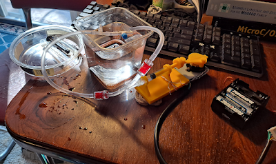
Printing! The latest version of the eyeball cradle.

The Vyper feeder also has an extrusion tension knob, another feature new to me. My first print appeared to have slight signs of under-extrusion, so I made a small adjustment, and left it alone otherwise. For future maintenance purposes, there appear to be easily accessible mechanisms for tightening the belts. 

I decided to be brave and print directly on the PEI build surface, instead of covering it with tape. This also worked wonderfully. I was able to pull all four of my prints off without even removing the plate to bend it. One of them (a large, flattish piece) even released itself from the surface after being left to cool long enough, and was lying there loose when I came to get it.

Two 3d-printed Wolf School amulets, one in dark red PLA (left) and one in bright orange PLA (right). Top/front view.
First print from Vyper (left) compared with first print from X-One 2 (right). Model by Thingiverse user Daniel_W.

I've seen some reviewers complain that the magnetic build surface doesn't have any slots or guides to fit into, so it can be a pain to line it up perfectly when sticking it back onto the bed after print removal. I re-seated it when assembling the printer and found that yes, it's a little tricky, given that the strong magnet will try to pull it down fast and fight your attempts to shift it. I don't consider this an important issue. So it demands a little more care and coordination - oh well. I'm more concerned that the PEI surface isn't a sticker. If it gets scratched or gouged, I think you have to replace the whole spring steel plate, for about $25. But one of my future goals is experimenting with other surfaces, so I may end up layering something removable on top of it anyway.

I used Cura to slice my models, as I do for the X-One. It doesn't have printer-dimension presets for the Vyper yet, but the documentation will tell you how to start from existing presets and change the numbers to fit the Vyper. The manufacturer also provides recommended PLA print settings, which I loaded in and tweaked to my liking. No problems here.

The bottom sides of the two amulets. Red (Vyper-printed) amulet has a very even surface with a regular marbled texture on it. Bottom amulet (printed on tape) has traditional smushed diagonal lines plus some irregularities from boundaries between tape strips.
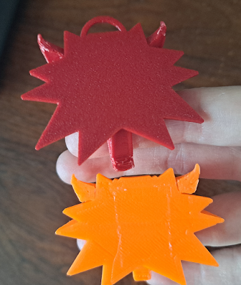
And the underside: first print from Vyper (top, textured PEI surface) compared with first print from X-One 2 (bottom, blue painter's tape). Model by Thingiverse user Daniel_W.

Print quality was great. I won't say "perfect," since I can see a few hints of wall irregularities, and the support situation on my first model was less than ideal. But I think quality is slightly better when compared with my very first print on the X-One (same model). I also haven't yet tried to really dial in the Cura settings.

After my initial test print, I put the Vyper straight to work on a new iteration of Atronach's eyeball (three parts, all PLA), and this went off without a hitch. I think that's a pretty good test for all the basic functionality. Prints I have yet to do include 1) something really detailed, like a miniature, 2) a print-in-place tolerance torture test, and 3) something in PETG.

A 3d-printed "eyeball" with a webcam mounted inside, sitting in its rotator cradle. Transparent nylon lines run like lines of longitude from holes around the "pupil" to the back of the eyeball.
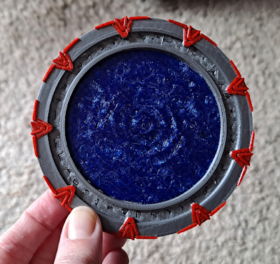
The latest eyeball. More about this later!

On the whole I'm very happy with this printer. It was on sale on Newegg, and I got it for about $350 with free shipping. I was a little concerned about quality as compared to e.g. a Prusa, but at half the price I was willing to risk it, and I think that has paid off.

Until the next cycle,
Jenny