I can finally show off the new and upgraded "Atronach's Eye!" I actually did this work last year, but never got the blog put together ... mainly because I wanted a demo video, and somehow, making that was such a scary little chore that I kept putting it off. (It took less than an hour, even though I had half-forgotten how to set everything up, so ... why, me? On the plus side, the Eye still worked perfectly after sitting around for months.)
 |
| The eye semi-assembled, showing the internals. |
With some 3D modeling skills under my belt, I was ready to try an upgrade of this old project. My objectives were threefold:
1. Improve the aesthetics and manufacturability of the housing
2. Get a camera in the eye and finally do some basic motion tracking
3. Add limit switches for the eye motion
The New Housing
I think Goal #1 was a complete success. (The colors are a little garish, maybe. I should try three instead of four next time.) Atronach was conceived as the genius loci of the house ... so for the case style, I tried to draw inspiration from fancy old furniture, especially of the "ball in claw foot" variety. The Hebrew lettering is a nod to golem legends, as it was in the original case design. I modeled most of the case parts in DesignSpark Mechanical, and used Meshmixer's sculpting tools to make the claw.
 |
| An exploded view of the case model in DesignSpark Mechanical (minus the claws). |
 |
| Claw sculpting in Meshmixer |
I had a variety of print difficulties -- first and perhaps worst, trouble with tolerances. In hindsight, a sixfold-symmetric design like this is not one I would recommend to beginners. It takes a lot of printing to discover that mistakes added up as you went round the circle, and your final pie-wedge doesn't fit. Trial and error ended up winning the day on this problem.
The flat panels (especially the ones with sharp corners) sometimes warped. I put a stop to this by turning up my heated bed temperature and shutting the printer enclosure. My printer's manual recommends leaving the door open when printing PLA, but it was rather cold in the house, and that may have contributed to the poor results.
 |
| A selection of completed case parts. Below: assembly of the base plate. |


Holes and pegs worked well enough for Ghost, but this model benefited greatly from the addition of some twisted-wire joins. They offer a more positive connection than the pegs while still allowing for disassembly. I used them to torque down the corners of the top and bottom panels, supporting the basic alignment established by the peg/hole connection in the center. The motor mounts are also wired to the bottom panels. I used beading wire for the purpose.
 |
| *wink* |
I included some holes on the inside walls of the case for mounting the controller boards. Rather than using screws, I tied the board mounting holes to the case mounting holes -- the boards are held in place by opposed tension.
Motion Tracking
The motor controller for the original Atronach's Eye was an ATTiny, but I needed something more sophisticated to process video from the camera. I got off to a bit of a false start by buying a CHIP mini-computer. It had the features I needed without any fluff -- one USB port for the camera, and wifi for communication with a desktop server -- and at $9 each, the boards were cheaper than their competitors. But it proved to be more trouble than it was worth.
 |
| A closer zoom, showing how the boards are mounted to the case. |
My first attempts to use the CHIP were mired in driver problems. Trying to communicate with it would bluescreen my old Windows 7 desktop (yes, really), and customer support didn't have much help to offer. This was several years ago, and I had nothing running Windows 10 at the time. I finally managed to talk to CHIP from the old scrap Linux machine, and get said Linux machine (which wouldn't recognize its network card) a working internet connection so I could actually install things on CHIP. By then I was exhausted, and set the project aside for a while.
By the time I was ready to go further, Next Thing Co. had folded, making it impossible to buy more CHIPs. I wanted multiple eyes (eventually) and didn't feel like investing even more struggle into a hardware platform I couldn't re-use. So I bought the standard Raspberry Pi: more expensive ($20-$25), but extremely established and reliable.
 |
| Finished! |
I set up a wifi connection between my (now Windows 10) desktop and the Pi without much issue, and got Python and OpenCV installed. The Pi had a USB port and no trouble recognizing my cheap tiny webcam. From there, I was able to get cracking on the video processing.
I used a dirt-simple method: detect pixels that have changed between one frame and the next, and compute the center of mass of the point cloud. It's not very good. Even with some thresholding and averaging added to the process, it's bad at telling the difference between actual moving objects and random camera noise. It's easily fooled into pointing at things like shadows. And it can't subtract changes caused by the camera's own motion, so tracking is not smooth. After the eye spots a moving object, it has to finish aiming at it before it can check whether it has changed position further; it cannot track while moving. As you can see from the video (below), it's terribly unresponsive. But it will look at me.
Since it's not precise at all, I simplified the motion further by making it discrete: I divided the visual field into nine regions. If the center of motion is not currently in the central nonet, motor control will rotate the eye by enough steps to aim at whichever nonet contains it.
Limit Switches
The original Atronach's Eye was programmed to move randomly. The processor would roughly track its orientation, but had no concrete way of knowing when it had rotated as far as possible in any direction ... so it would occasionally run it past its range and stall the motors. This didn't seem to hurt the steppers any, but stalling motors isn't a nice thing to do, and this was lazy on my part. So I really wanted to add some limit sensors to the new version.
Unfortunately, this didn't work out, and will have to wait for yet another version of the eye housing. Setting limits on the motion of a spherical object rolling in a cradle is just obnoxiously hard. The extended lip around the camera cord port at the back of the eyeball was supposed to be part of the limit sensor. Wrapped with aluminum foil, it would serve as one switch contact, and touch one of four partner contacts on the underside of the cradle whenever the eye rolled far enough over. In practice, I had huge trouble getting the angle and contact height correct so that they would actually touch. I became desperate to get the eyeball working, and this became a problem for another time.
In lieu of having limit sensors, the eyeball controller does a startup calibration routine. It drives the eyeball into motor-stall territory along each axis, then (using that as a known position) returns it to center. It then moves the eye a fixed number of motor steps to transition it between its nine possible discrete positions. This is control by dead reckoning, and is not guaranteed to be reliable over the long term ... recalibration might be needed from time to time. But in my tests, it seems to work well enough.
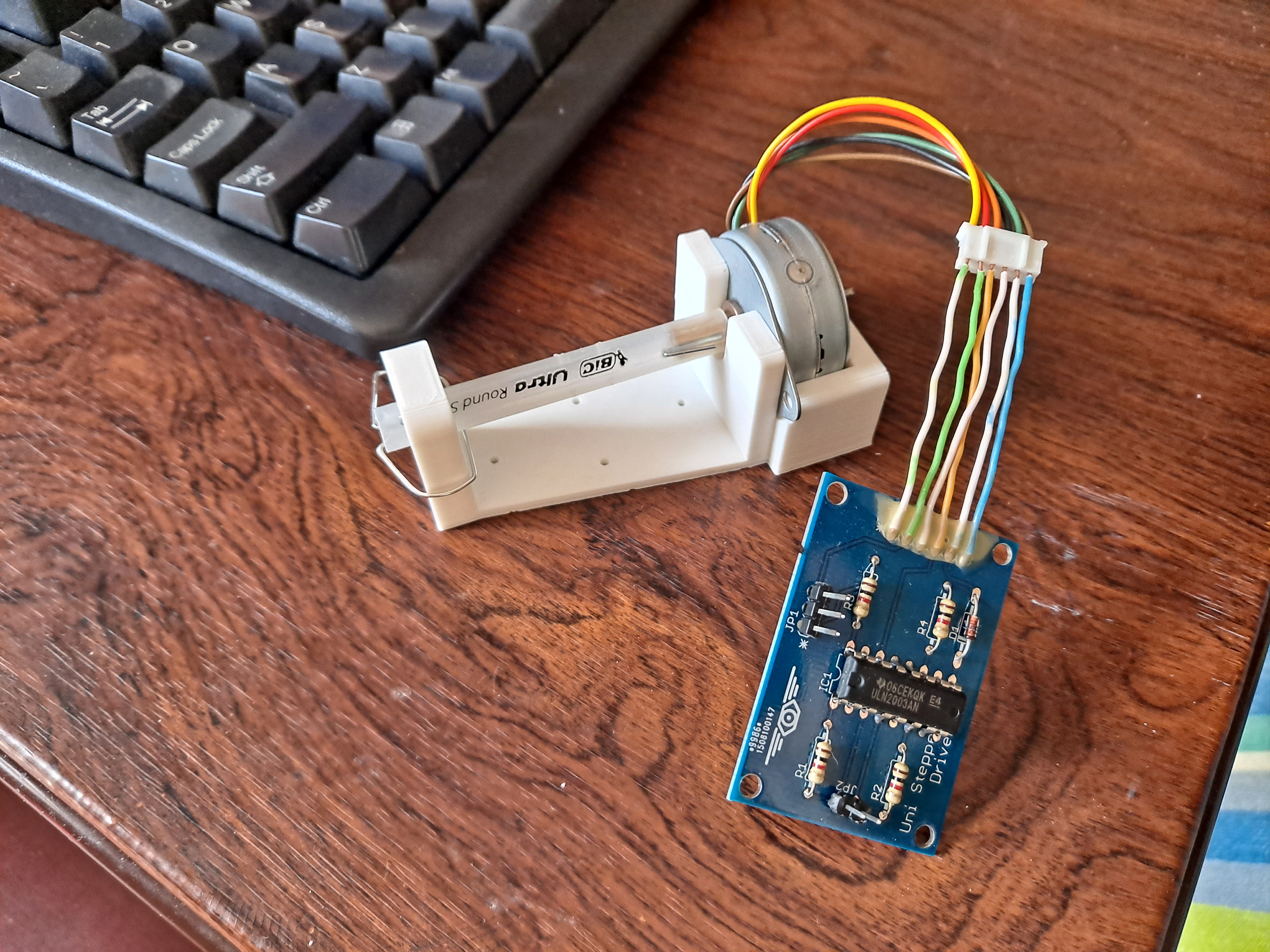 |
| Motor mount and driver board. |
Future Work
*I still need limit sensors, obviously.
*The motion of the eyeball in the cradle is not as smooth as I would like. I tied nylon threads across the seam of the ball in order to stop it from catching on the cradle's edge. I probably need to add more of these, or I could consider some sort of bearing.
*I'd like the eye to have a greater range of motion. This is affected by the diameter of the cradle and the placement of the tendon attachments.
*I've had trouble with the differential eye tendons getting slack in them, which causes a delay in motion when the eye changes direction. This is a mechanical issue I need to figure out.
*I'm still using my favorite two-wire unipolar stepper motor controllers. They provide no way to cut power to the motor coils, which means that even if the eye is not moving, the motors sit there and get toasty-warm. The eye is intended for long-term continuous operation, so this is not really what I want to happen. I need a power cutoff.
*More advanced image processing and tracking algorithms.
No comments:
Post a Comment