I present an upgrade of the poor person's first hydraulic system in which I have solved some of its major problems and achieved a meaningful performance boost. This demo has now advanced from "barely goes through the motions" to "demonstrates practical functionality." Hydraulic system Version 2 was able to lift about 16 g (0.5 oz.) of coins on the end of a lever, and to repeat this motion over many pressurize/depressurize cycles.
The basic architecture of the system was identical to that of Version 1, but I traded out both the pump and the actuator.
The Pump
I replaced the syringe pump I built last year with my newly completed peristaltic pump. I've already showcased the pumps in a previous article. The main benefits of switching to the peristaltic pump were increased flow rate and improved regularity of flow. The syringe pump was powerful but miserably slow. The high friction of the rubber seal on the syringe plunger made it prone to stalling the motor if the speed was not set with caution. And since the syringe pump has very distinct intake/exhaust cycles, it has a pulsating output flow that becomes very pronounced at low speeds. (As in, if you don't have a big enough pressure reservoir to soak up that variation, you have to wait for the exhaust cycle before your actuator will even move.) The syringe pump also incorporated a pair of check valves, which were very bad about trapping air bubbles. These bubbles wasted some of the pump's work by expanding and compressing as it cycled, making room for water that *should* have gone into the pressurized volume to stay inside the pump. And lastly ... the syringe pump leaked. The seal in the syringe clearly wasn't perfect, and water would leak out the back at times. I can only imagine that this would have gotten worse as the pump aged.
The peristaltic pump trades much of the syringe pump's high maximum pressure for a more reasonable flow rate. Its output pulsates slightly, since the water moves through the tubing in "pockets" captured between each pair of rollers, but it's much more regular than the syringe pump. And it has no seals; there is no direct contact between the fluid and the pump mechanicals.
For a stronger comparison, I used the same stepper motor and gear assembly (unknown model, powered by 12 V) to drive both pumps.
The Actuator
In hydraulic system Version 1, a second syringe functioned as a linear actuator. At the pressure level where my system was operating, friction losses turned out to be a major problem. I couldn't put a load on the syringe because the pump was only equal to overcoming the resistance of the sliding seal; any extra load prevented it from extending the syringe. So the demo consisted of the syringe filling (very slowly) as water was pumped into it during the pressurize cycle, and being manually emptied by me during the depressurize cycle (since there was no load to passively push it closed again).
Rather than try to find better syringes, I thought to move away from them entirely. Those friction losses seemed like such a waste. But what other sort of hydraulic actuator could I use? The option I came up with was an inflateable bladder. What I had in mind was something very simple: literally an inflateable bag that, when pumped full of fluid, would change shape so as to move a joint or other mechanical element. It would have little to no friction losses to waste the effort of the pump. And it would have no sliding rubber seals to stiffen, shrink, or wear out over time.
As interesting as the idea seemed, I once again found it difficult to purchase what I wanted. There are such things as "lifting bags" or "air bag jacks," but they're designed for much larger applications. I think AliExpress had a few inflatable bags on the order of a few inches per side; still too large. I concluded that I would have to make my new actuators myself. I hit on the idea of cutting and heat-sealing plastic bags to create tiny bladders in any size or shape I wanted. Since I did not have a dedicated heat sealer, I heat-sealed my bladders by sandwiching the layers of plastic between two layers of aluminum foil, and running my soldering iron across the top of the foil.
In addition to sealing the edges to form the shape of the bladder, I also needed a way to include a valve stem - so I could connect the bladder to a tube and get fluid in and out. At first I was hoping I could scavenge some plastic tubing from my collection of mechanical pencils, cut it up into stems, and heat-seal the bladder walls directly to those stems. This never worked. The tubes and the plastic bags I was working with were likely different materials, and distinct types of plastic resist adhering to each other. I also tried sealing one edge of the bladder with silicone sealant and inserting the stem between the two layers of plastic, through the silicone. These seals always leaked. The silicone seemed to adhere to both the bag and the stem well enough, but didn't fill the gaps perfectly.
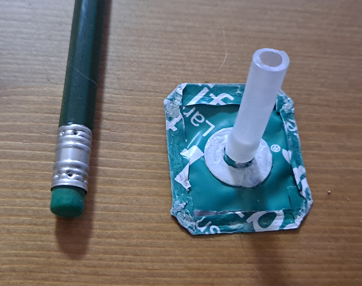
What eventually worked out was a 3d-printed valve stem with a circular flange, inserted not through an edge of the bladder but through one of its flat sides. The flange was one piece with the stem, and was attached to the inside of the bladder; the stem poked out through a hole in the plastic sheet. The second piece of the assembly was a plastic ring that fitted around the stem and attached to the outside of the bladder. I applied a ring of cyanoacrylate adhesive (Super Glue) between the flange or ring and each side of the plastic sheet. This finally gave me a watertight seal around the valve stem.

I still had problems with the bladders leaking at the edges, from holes next to the seal. This led me to experiment with some different kinds of plastic. All my plastic films are salvaged, and I don't know enough about package manufacturing to be sure what any of them are. They're likely all different variants of polyethylene or polypropylene. My first attempts used a smooth, soft, transparent plastic from packing air pillows (which felt very similar to the plastic from bread bags, for instance). It was inclined to melt into swiss cheese if I applied just a little too much heat when trying to seal it. Ramen noodle packets are made from a stiffer, more crinkly plastic. This heat-sealed reasonably well. But the real winner was the tough, thick, pewter-gray plastic from the bags that Thriftbooks sends my used paperbacks in. (I expect to have a never-ending supply of this.) Not only is this plastic very tear-resistant, but when I melt two layers of it together, it really fuses - such that the seal can't be peeled apart without ripping the plastic next to it. I think this is important for the durability of the bladders. For typical plastic packaging, heat seals that peel apart when the end user wants to open it are often a positive - but I don't want the water pressure to slowly work my bladders open over repeated cycles.
Even when using this heavier plastic, I had to be very careful that my aluminum foil sandwich didn't conduct heat to the wrong part of it and melt a hole next to the seal. Now that I've proven the concept, I think I'm going to buy myself a real heat-sealer.
After many trials, I produced a small bladder that was water-tight. I gave it a simple machine to actuate, in the form of a wooden lever attached to a piece of cardboard with a sloppy pivot. I mounted two pennies and two quarters on the end of the lever as a load.
The Results
This is the demo I wanted last year. To start with, the fact that it can actually raise a load is a major improvement. The speed of operation is also much more reasonable. I am now ready to move past this toy demo and think about final pump designs and real applications.
One issue that remains to be solved, which you may notice in the video, is that the lever experiences (relatively) small oscillations of position, which are likely following the pulsating outflow of the pump. In a real system with control electronics guiding the actuator, this would interfere with precise positioning of the lever. I think this could be mitigated by a larger pressurized reservoir (the demo system has none to speak of - the tubing makes up the entire pressurized volume) and use of a pair of two-way valves instead of a single three-way valve, which would allow the bladder to be closed off from the pump's influence once inflated to the desired size.
The one part I haven't tried to improve on yet is the cheapo pressure relief valve. For the demo, I basically just closed it all the way. The peristaltic pump has a little more "give" than the syringe pump, and seems to be able to drive against its maximum pressure without stalling. If I want a better valve, I may end up having to build one myself. We'll see.
For now, I'm very pleased with how far I've come, and hope to be showing you a hydraulic robot or two, someday.
Until the next cycle,
Jenny
No comments:
Post a Comment